Saturday, June 20, 2009
%LEL
The lower explosive limit (LEL) or lower flammable limit (LFL) of a combustible gas is the smallest amount of the gas that supports a self-propagating flame when mixed with air (or oxygen) and ignited. In gas-detection systems, the amount of gas present is specified as a percentage (%) LEL. Zero percent (0%) LEL denotes a combustible gas-free atmosphere. One hundred percent (100%) lower explosive limit denotes an atmosphere in which gas is at its lower flammable limit. The relationship between percent LEL and percent by volume differs from gas to gas.
Wednesday, December 27, 2006
Phased Migration for the μXL
Phased migration for the μXL is a two-step upgrade method on a component basis, which reduces the required investment and manpower, and shortens the upgrade period.
Step1 : Upgrading of HMI
Upgrading of HMI brings in the latest HMI environment and network capability, surely one of the most important issues.
Step1 : Upgrading of HMI
Upgrading of HMI brings in the latest HMI environment and network capability, surely one of the most important issues.

Step2 : Upgrading of the control units
Using existing field wiring, the latest I/Os are provided with full compatibility of functions, interface and cabinet layout.

Phased Migration of Centum V, Centum XL
Phased migration for the CENTUM V, CENTUM-XL is a three-step upgrade method on a component basis, which reduces the required investment and manpower, and shortens the upgrade period.
Upgrading of HMI brings in the latest HMI environment and network capability, surely one of the most important issues.

By utilizing the existing field wiring and I/O cards, the latest control functions are provided, while greatly improving performance and application capacity.
Step 3 : Upgrading of I/Os
Using existing field wiring, the latest I/Os are provided with full compatibility of functions, interface and cabinet layout.

Why Migration of DCS Systems ?
To generate the maximum return with the minimum investment, it is required to migrate the legacy CENTUM V, CENTUM-XL and μXL DCS systems into the new production plant control systems with the latest technology so as to take part in the competition of the 21st century.
The network functionality of legacy systems is not sufficient for 21st-century control systems. Adding network capability to these system produces the following benefits
-By linking to supervisory information system, dynamic adjustment of operations to meet market demands
-Productivity improvement by linking to Advanced Process Control (APC)
-Improvement of operational efficiency by linking to Advanced Operation Assistance (AOA)
Thursday, November 23, 2006
HART Protocol Overview
LEADING COMMUNICATION TECHNOLOGY
The HART Protocol is the leading communication technology used with smart process instrumentation today. The HART Protocol continues to grow in popularity and recognition in the industry as a global standard for smart instrument communication. More than two-thirds of all smart instruments shipping today communicate using the HART Protocol.
EASY TO USE
HART is field-proven, easy to use and provides highly capable two-way digital communication simultaneously with the 4-20mA analog signaling used by traditional instrumentation equipment.
UNIQUE COMMUNICATION SOLUTION
Unlike other digital communication technologies, the HART Protocol provides a unique communication solution that is backward compatible with the installed base of instrumentation in use today. This backward compatibility ensures that investments in existing cabling and current control strategies will remain secure well into the future.
Designed to compliment traditional 4-20mA analog signaling, the HART Protocol supports two way digital communications for process measurement and control devices. Applications include remote process variable interrogation, cyclical access to process data, parameter setting and diagnostics.
STRUCTURE
Specification of the HART protocol is based largely on the OSI 7-Layer Communication Model (see Figure 1).
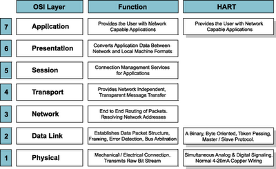
Figure 1. OSI 7-Layer Model
The HART protocol specifications directly address 3 layers in the OSI model: the Physical, Data Link and Application Layers. The Physical Layer connects devices together and communicates a bit-stream from one device to another. It is concerned with the mechanical and electrical properties of the connection and the medium (the copper wire cable) connecting the devices. Signal characteristics are defined to achieve a raw uncorrected reliability (see the FSK Physical Layer Specification).
While the Physical Layer transmits the bit stream, the Data Link Layer is responsible for reliably transferring that data across the channel. It organizes the raw bit stream into packets (framing), adds error detection codes to the data stream and performs Media Access Control (MAC) to insure orderly access to the communication channel by both master and slave devices.
The bit stream is organized into 8-bit bytes that are further grouped into messages. A HART transaction consists of a master command and a slave response. Media access consists of token passing between the devices connected to the channel. The passing of the token is implied by the actual message transmitted. Timers are used to bound the period between transactions. Once the timer expires, control of the channel is relinquished by the owner of the token. For more information see the Data Link Layer Specification.
The Application Layer defines the commands, responses, data types and status reporting supported by the Protocol. In addition, there are certain conventions in HART (for example how to trim the loop current) that are also considered part of the Application Layer. While the Command Summary, Common Tables and Command Response Code Specifications all establish mandatory Application Layer practices (e.g. data types, common definitions of data items, and procedures), the Universal Commands specify the minimum Application Layer content of all HART compatible devices.
Thursday, November 16, 2006
Subnet Masks and Subnetting
A subnet allows the flow of network traffic between hosts to be segregated based on a network configuration. By organizing hosts into logical groups, subnetting can improve network security and performance.
Subnet Mask
Perhaps the most recognizable aspect of subnetting is the subnet mask. Like IP addresses, a subnet mask contains four bytes (32 bits) and is often written using the same "dotted-decimal" notation. For example, a very common subnet mask in its binary representation
11111111 11111111 11111111 00000000 is typically shown in the equivalent, more readable form 255.255.255.0
11111111 11111111 11111111 00000000 is typically shown in the equivalent, more readable form 255.255.255.0
Applying a Subnet MaskA subnet mask neither works like an IP address, nor does it exist independently from them. Instead, subnet masks accompany an IP address and the two values work together.
Applying the subnet mask to an IP address splits the address into two parts, an "extended network address" and a host address.
For a subnet mask to be valid, its leftmost bits must be set to '1'. For example,
00000000 00000000 00000000 00000000 is an invalid subnet mask because the leftmost bit is set to '0'.
Conversely, the rightmost bits in a valid subnet mask must be set to '0', not '1'. Therefore,
11111111 11111111 11111111 11111111 is invalid.
All valid subnet masks contain two parts: the left side with all mask bits set to '1' (the extended network portion) and the right side with all bits set to '0' (the host portion), such as the first example above.
Understanding IP Addressing
Every computer that communicates over the Internet is assigned an IP address that uniquely identifies the device and distinguishes it from other computers on the Internet. An IP address consists of 32 bits, often shown as 4 octets of numbers from 0-255 represented in decimal form instead of binary form.
For example, the IP address 168.212.226.204
in binary form is 10101000.11010100.11100010.11001100.
But it is easier for us to remember decimals than it is to remember binary numbers, so we use decimals to represent the IP addresses when describing them. However, the binary number is important because that will determine which class of network the IP address belongs to. An IP address consists of two parts, one identifying the network and one identifying the node, or host. The Class of the address determines which part belongs to the network address and which part belongs to the node address. All nodes on a given network share the same network prefix but must have a unique host number.
Class A Network -- binary address start with 0, therefore the decimal number can be anywhere from 1 to 126. The first 8 bits (the first octet) identify the network and the remaining 24 bits indicate the host within the network. An example of a Class A IP address is 102.168.212.226, where "102" identifies the network and "168.212.226" identifies the host on that network.
Class B Network -- binary addresses start with 10, therefore the decimal number can be anywhere from 128 to 191. (The number 127 is reserved for loopback and is used for internal testing on the local machine.) The first 16 bits (the first two octets) identify the network and the remaining 16 bits indicate the host within the network. An example of a Class B IP address is 168.212.226.204 where "168.212" identifies the network and "226.204" identifies the host on that network.
Class C Network -- binary addresses start with 110, therefore the decimal number can be anywhere from 192 to 223. The first 24 bits (the first three octets) identify the network and the remaining 8 bits indicate the host within the network. An example of a Class C IP address is 200.168.212.226 where "200.168.212" identifies the network and "226" identifies the host on that network.
Class D Network -- binary addresses start with 1110, therefore the decimal number can be anywhere from 224 to 239. Class D networks are used to support multicasting.
Class E Network -- binary addresses start with 1111, therefore the decimal number can be anywhere from 240 to 255. Class E networks are used for experimentation. They have never been documented or utilized in a standard way.
Subscribe to:
Comments (Atom)